TM 1-1520-238-23
9-290
9.77.
MULTICHANNEL DIMMING CONTROLLER CHASSIS DISASSEMBLY/ASSEMBLY
(AVIM) – continued
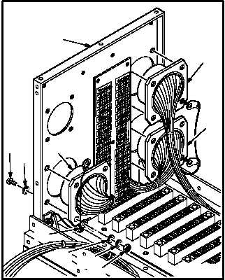
(5) Remove receptacles (A403)J2 (38),
(A403)J3 (39), and (A403)J4 (40) from panel
(2).
NOTE
On receptacle (A403)J4, only the
mounting hardware on the lower left–
hand corner (looking from rear) has a
grounding terminal lug installed.
On receptacle (A403)J2 and
(A403)J3, only the mounting hardware
on the lower right–hand corner (looking
from rear) has a grounding terminal lug
installed.
After removing mounting hardware
from receptacles (A403)J2, (A403)J3,
and (A403)J4, allow receptacles to re-
main inside front panel until ready to
remove the entire harness assembly
from controller chassis.
(a) Hold 12 screws (41). Remove nuts (42),
lockwashers (43), washers (44), and ter-
minal lugs (45) from rear of receptacles
(38), (39), and (40).
(b) Remove 12 screws (41) and washers (46)
from front of panel (2).
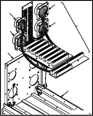
(6) Remove harness (15) from base (7) and pan-
el (2).
(a) Slide receptacles (A403)J1 (31),
(A403)J2 (38), (A403)J3 (39), and
(A403)J4 (40) out from panel (2).
(b) Support harness (15) components with
both hands. Remove harness (15) from
base (7) and panel (2).
GO TO NEXT PAGE
M04-4208-9
2
41
46
45
38
40
39
42
44
43
38
40
31
M04-4208-10
7
2
15
39


