TM 1-1520-238-23
Change 2
11-101
11.15.
MAIN ROTOR PITCH LINK DISASSEMBLY/ASSEMBLY – continued
e. Check all removed bushing(s) and/or bear-
ing(s) for wear (para 11.4).
11.15.6. Assembly
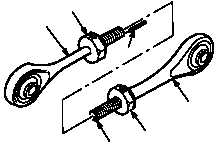
a. Install nuts (4) on rod ends (1) and (2).
(1) Install nuts (4) to the maximum limit of the
threaded portions of both rod ends (1) and
(2).
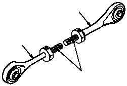
(2) Insert alinement pin (5) in alinement hole (6).
(3) Aline rod ends (1) and (2).
(4) Draw alinement line (7) length of threaded
portion of rod ends (1) and (2).
(5) Separate rod end (1) from rod end (2).
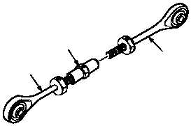
b. Install rod ends (1) and (2) on barrel (3).
(1) Rotate barrel (3) two complete turns on rod
end (2).
(2) Hold barrel (3) while rotating rod end (1) two
complete turns in barrel (3).
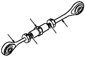
(3) Mate rod end alinement lines (7).
(4) Hold rod ends (1) and (2) securely.
NOTE
Bearing alinement pin will be entering
bearing assembly alinement hole when
both rod ends appear in barrel inspection
holes. If binding occurs, loosen barrel.
GO TO NEXT PAGE
M04-1731-3
4
2
5
6
4
1
M04-1731-4
2
1
7
1
M04-1731-5
3
2
M04-1731-6
2
3
7
7
1