M04-1636-8
3
2
12
TM 1-1520-238-23
16-14
Change 8
16.3.
PYLON RACK EJECTOR IMPULSE CARTRIDGE REMOVAL/INSTALLATION - continued
16.3.6. Installation
NOTE
If housing is to be installed with a car-
tridge, perform steps b., c., and d. only.
If housing and cartridge are to be
installed, perform steps b. through o.
If housing is to be installed without a
cartridge, perform step a only. Car-
tridge housing is to be installed in re-
verse position, for safety.
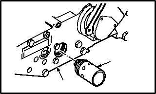
a. Install housing (3) 180 in reverse position, to
show no cartridge installed.
b. Install housing (3) in rack (2). Torque housing
(3) to 85 INCH-POUNDS.
c. Lockwire housing (3) to ejector bolt (12). Use
wire (item 224, App F).
d. Inspect (QA).
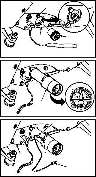
e. Calibrate and install ejector test set (7) (para
16.8).
f. Check test set indicator (8) for allowable con-
tact pin length. Indicator should read between
0.025 and 0.065 INCH.
g. Replace contact pin if indicator (8) does not
read between 0.025 and 0.065 INCH (para
16.19).
h. Check for static electricity in rack (2).
(1) Insert multimeter positive lead (9) in test set
meter jack (10). Use multimeter.
(2) Place multimeter negative lead (11) on any
helicopter ground.
(3) Check for voltage on multimeter. Repeat step
h if voltage is present. If voltage is not present
go to step i.
i. Remove ejector test set from pylon rack (para
16.8).
GO TO NEXT PAGE
2
3
M04-1636-9
M04-1636-6
8
7
M04-1636-7
11
10
9
2