TM 1-1520-238-23
4-654
Change 1
4.183.
NO. 2 ENGINE POWER AVAILABLE SPINDLE (PAS) RIGGING PROCEDURE – continued
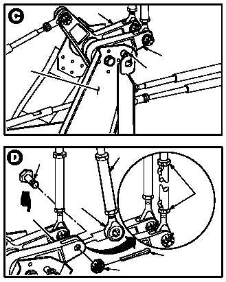
f. Install –3 rig pin (8) fully in bracket (9) and
bellcranks (10) and (11).
NOTE
If bellcrank does not aline, go to step g. If
bellcrank does aline, go to step l.
g. Adjust No. 2 power quadrant connecting link
(12) to aline with bellcrank (10).
(1) Remove and discard cotter pin (13).
(2) Hold bolt (14). Remove nut (15).
(3) Remove bolt (14) from bellcrank (10) and link
(12).
(4) Remove lockwire from link (12).
(5) Loosen two jam nuts (16) at ends of link (12).
(6) Adjust length of link (12) as needed. Aline link
rod end (17) with bellcrank (10).
h. Install link (12) on bellcrank (11). Torque nut
(15) 14 to 18 INCH-POUNDS. Torque two jam
nuts (16) to 25 INCH-POUNDS.
(1) Install bolt (14) through bellcrank (11) and rod
end (17).
(2) Install nut (15) on bolt (14).
(3) Hold bolt (14). Torque nut (15) to 14 INCH-
POUNDS. Use torque wrench.
(4) Increase torque to aline cotter pin hole, but do
not exceed 18 INCH-POUNDS.
(5) Install new cotter pin (13).
(6) Torque two jam nuts (16) to 25 INCH-
POUNDS. Use torque wrench.
(7) Lockwire two jam nuts (16) to link (12). Use
wire (item 226, App F).
GO TO NEXT PAGE
11
10
M04-1208-12
9
8
M04-1208-13A
14
10
17
15
16
13
12