TM 1-1520-238-23
Change 8
11-107
11.16.
LOAD BEARING MAIN ROTOR SCISSOR REMOVAL/INSTALLATION – continued
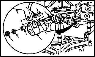
c. Install other side of scissor (1).
(1) Install bearing (17) and laminated washer
(16) between scissor (1) and shoe (2).
(2) Install bushing (18) in scissor (1) and shoe
(2).
CAUTION
Threads of bolt and nut shall be clean
and compound free. Contaminated
threads can cause improper torque,
which may cause damage to flight control
system.
(3) Apply a light coat of corrosion preventive
compound to shank of bolt (14). Use
corrosion preventive compound (item 62A,
App F).
(4) Install bolt (14) through washer (15) (with
countersunk side of washer adjacent to bolt
head), scissor (1), laminated washer (16),
bearing (17), shoe (2), and bushing (18).
(5) Install washer (13) and nut (12).
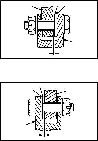
d. Check for total axial play of 0.001 to 0.003
INCH between bearings (9) and (17) and shoe
(2).
(1) Measure clearance between shoe (2) and
bearing (17).
(2) Measure clearance between shoe (2) and
bearing (9).
(3) If the sum of the clearances from steps (1)
and (2) are between 0.001 and 0.0010 inch,
go to step e.
(4) Remove scissor (1) from shoe (2) if clear-
ances are not within limits.
(5) Add or peel laminated washers (8) and (16)
using equal thickness as required to within
0.002 INCH on both sides of scissor mount-
ing points.
(6) Repeat steps b. through d.
GO TO NEXT PAGE
14
2
12
13
18
1
16
M04-1721-6
17
15
M04-1721-7B
0.001
0.003
2
17
16
1
M04-1721-10B
0.001
0.003
1
8
9
2