TM 1-1520-238-23
Change 3
11-111
11.17.
LOAD BEARING SCISSOR DISASSEMBLY/ASSEMBLY – continued
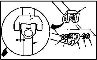
NOTE
Refer to notes taken when measuring
clearance to get proper laminated wash-
er thickness.
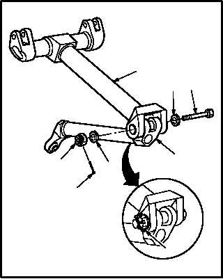
b. Install lower arm (1) on upper arm (2). Torque
nut (5) 100 to 200 INCH-POUNDS.
(1) Aline lower arm (1) with upper arm (2).
NOTE
Use equal thickness, within 0.002 INCH,
of laminated washers on both sides as
required, to limit total axial play to 0.001
to 0.003 INCH.
(2) Peel laminated washers (9) as needed to ob-
tain proper clearance.
(3) Position two laminated washers (9) and bear-
ings (8).
NOTE
Verify axial play of 0.001 to 0.003 INCH
clearance between upper arm and lower
arm.
(4) Install bolt (4) through washer (7) (with coun-
tersunk side of washer adjacent to bolt head),
upper arm (2), and lower arm (1).
(5) Install washer (6) and nut (5) on bolt (4).
(6) Hold bolt (4). Use open end wrench.
(7) Torque nut (5) to 100 INCH-POUNDS. Use
torque wrench and socket.
(8) Increase torque to aline cotter pin hole, but do
not exceed 200 INCH-POUNDS.
(9) Install new cotter pin (3).
c. Inspect (QA).
d. Install load bearing main rotor scissor (para
11.16).
END OF TASK
M04-1725-4B
2
8
9
8
1
2
0.001
0.003
1
9
M04-1725-6
2
7
4
1
6
3
5
3


