TM 1-1520-238-23
11-110
Change 2
11.17.
LOAD BEARING SCISSOR DISASSEMBLY/ASSEMBLY – continued
11.17.5. Inspection
a. Check removed and attaching parts for
scratches and elongation.
(1) Damage in a bore area within 1-1/2 times the
bore diameter is not to exceed 10 percent of
the material thickness or 0.040 INCH, which-
ever is less.
b. Check removed and attaching parts for
cracks. None allowed.
c. Check removed and attaching parts for wear
(para 11.5).
d. Check removed and attaching parts for corro-
sion (para 1.49).
e. Check all installed bushing(s) and/or bear-
ing(s) for wear (para 11.5).
f. Check all removed bushing(s) and/or bear-
ing(s) for wear (para 11.4).
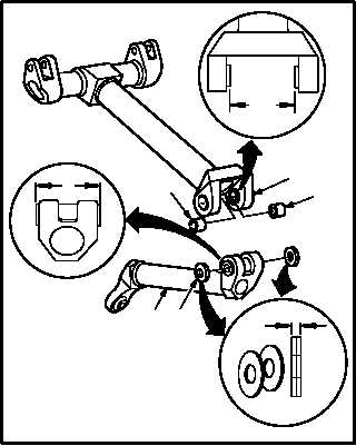
11.17.6. Assembly
a. Measure clearance between lower arm (1) and
upper arm (2).
(1) Measure combined thickness of two bearings
(8). Use caliper set.
(a) Record this as dimension A.
(2) Measure width of lower arm (1) lug. Use
caliper set.
(a) Record this as dimension B.
(3) Install two bushings (10) in upper arm (2).
(4) Measure inside dimension of upper arm (2)
between bushings (10). Use caliper.
(a) Record this as dimension C.
(5) Subtract total of dimension A and B from di-
mension C.
(6) The result equals combined thickness of two
laminated washers plus axial play.
(a) Record measurement for reference dur-
ing assembly.
GO TO NEXT PAGE
A
B
M04-1725-3
10
2
10
1
8
C