TM 1-1520-238-23
Change 2
11-113
11.17A. SECONDARY SCISSOR DISASSEMBLY/ASSEMBLY – continued
11.17A.5. Inspection
a. Check removed and attaching parts for
scratches and elongation.
(1) Damage in a bore area within 1-1/2 times the
bore diameter is not to exceed 10 percent of
the material thickness or 0.040 INCH, which-
ever is less.
b. Check removed and attaching parts for
cracks. None allowed.
c. Check removed and attaching parts for wear
(para 11.5).
d. Check removed and attaching parts for corro-
sion (para 1.49).
e. Check all installed bushing(s) and/or bear-
ing(s) for wear (para 11.5).
f. Check all removed bushing(s) and/or bear-
ing(s) for wear (para 11.4).
11.17A.6. Assembly
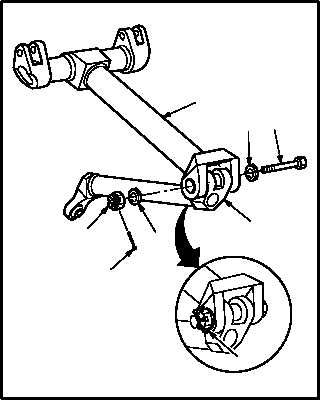
a. Install lower arm (1) on upper arm (2). Torque
nut (5) 100 to 200 INCH-POUNDS.
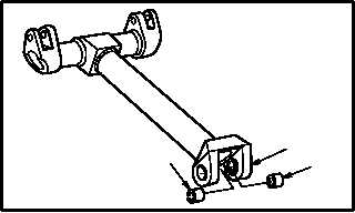
(1) Install two bushings (8) in upper arm (2).
(2) Aline lower arm (1) with upper arm (2).
(3) Install bolt (4) through washer (7) (with coun-
tersunk side of washer adjacent to bolt head),
upper arm (2), and lower arm (1).
(4) Install washer (6) and nut (5) on bolt (4).
(5) Hold bolt (4). Use open end wrench.
(6) Torque nut (5) to 100 INCH-POUNDS. Use
torque wrench and socket.
(7) Increase torque to aline cotter pin hole, but do
not exceed 200 INCH-POUNDS.
(8) Install new cotter pin (3).
b. Inspect (QA).
c. Install secondary main rotor scissor (para
11.18).
END OF TASK
M04-1726-2
8
2
8
M04-1726-3
2
7
4
1
6
3
5
3


